1.4: IV. Using Central Ideas to Develop an Explanation for Intriguing Phenomena
- Page ID
- 15104
\( \newcommand{\vecs}[1]{\overset { \scriptstyle \rightharpoonup} {\mathbf{#1}} } \)
\( \newcommand{\vecd}[1]{\overset{-\!-\!\rightharpoonup}{\vphantom{a}\smash {#1}}} \)
\( \newcommand{\id}{\mathrm{id}}\) \( \newcommand{\Span}{\mathrm{span}}\)
( \newcommand{\kernel}{\mathrm{null}\,}\) \( \newcommand{\range}{\mathrm{range}\,}\)
\( \newcommand{\RealPart}{\mathrm{Re}}\) \( \newcommand{\ImaginaryPart}{\mathrm{Im}}\)
\( \newcommand{\Argument}{\mathrm{Arg}}\) \( \newcommand{\norm}[1]{\| #1 \|}\)
\( \newcommand{\inner}[2]{\langle #1, #2 \rangle}\)
\( \newcommand{\Span}{\mathrm{span}}\)
\( \newcommand{\id}{\mathrm{id}}\)
\( \newcommand{\Span}{\mathrm{span}}\)
\( \newcommand{\kernel}{\mathrm{null}\,}\)
\( \newcommand{\range}{\mathrm{range}\,}\)
\( \newcommand{\RealPart}{\mathrm{Re}}\)
\( \newcommand{\ImaginaryPart}{\mathrm{Im}}\)
\( \newcommand{\Argument}{\mathrm{Arg}}\)
\( \newcommand{\norm}[1]{\| #1 \|}\)
\( \newcommand{\inner}[2]{\langle #1, #2 \rangle}\)
\( \newcommand{\Span}{\mathrm{span}}\) \( \newcommand{\AA}{\unicode[.8,0]{x212B}}\)
\( \newcommand{\vectorA}[1]{\vec{#1}} % arrow\)
\( \newcommand{\vectorAt}[1]{\vec{\text{#1}}} % arrow\)
\( \newcommand{\vectorB}[1]{\overset { \scriptstyle \rightharpoonup} {\mathbf{#1}} } \)
\( \newcommand{\vectorC}[1]{\textbf{#1}} \)
\( \newcommand{\vectorD}[1]{\overrightarrow{#1}} \)
\( \newcommand{\vectorDt}[1]{\overrightarrow{\text{#1}}} \)
\( \newcommand{\vectE}[1]{\overset{-\!-\!\rightharpoonup}{\vphantom{a}\smash{\mathbf {#1}}}} \)
\( \newcommand{\vecs}[1]{\overset { \scriptstyle \rightharpoonup} {\mathbf{#1}} } \)
\( \newcommand{\vecd}[1]{\overset{-\!-\!\rightharpoonup}{\vphantom{a}\smash {#1}}} \)
\(\newcommand{\avec}{\mathbf a}\) \(\newcommand{\bvec}{\mathbf b}\) \(\newcommand{\cvec}{\mathbf c}\) \(\newcommand{\dvec}{\mathbf d}\) \(\newcommand{\dtil}{\widetilde{\mathbf d}}\) \(\newcommand{\evec}{\mathbf e}\) \(\newcommand{\fvec}{\mathbf f}\) \(\newcommand{\nvec}{\mathbf n}\) \(\newcommand{\pvec}{\mathbf p}\) \(\newcommand{\qvec}{\mathbf q}\) \(\newcommand{\svec}{\mathbf s}\) \(\newcommand{\tvec}{\mathbf t}\) \(\newcommand{\uvec}{\mathbf u}\) \(\newcommand{\vvec}{\mathbf v}\) \(\newcommand{\wvec}{\mathbf w}\) \(\newcommand{\xvec}{\mathbf x}\) \(\newcommand{\yvec}{\mathbf y}\) \(\newcommand{\zvec}{\mathbf z}\) \(\newcommand{\rvec}{\mathbf r}\) \(\newcommand{\mvec}{\mathbf m}\) \(\newcommand{\zerovec}{\mathbf 0}\) \(\newcommand{\onevec}{\mathbf 1}\) \(\newcommand{\real}{\mathbb R}\) \(\newcommand{\twovec}[2]{\left[\begin{array}{r}#1 \\ #2 \end{array}\right]}\) \(\newcommand{\ctwovec}[2]{\left[\begin{array}{c}#1 \\ #2 \end{array}\right]}\) \(\newcommand{\threevec}[3]{\left[\begin{array}{r}#1 \\ #2 \\ #3 \end{array}\right]}\) \(\newcommand{\cthreevec}[3]{\left[\begin{array}{c}#1 \\ #2 \\ #3 \end{array}\right]}\) \(\newcommand{\fourvec}[4]{\left[\begin{array}{r}#1 \\ #2 \\ #3 \\ #4 \end{array}\right]}\) \(\newcommand{\cfourvec}[4]{\left[\begin{array}{c}#1 \\ #2 \\ #3 \\ #4 \end{array}\right]}\) \(\newcommand{\fivevec}[5]{\left[\begin{array}{r}#1 \\ #2 \\ #3 \\ #4 \\ #5 \\ \end{array}\right]}\) \(\newcommand{\cfivevec}[5]{\left[\begin{array}{c}#1 \\ #2 \\ #3 \\ #4 \\ #5 \\ \end{array}\right]}\) \(\newcommand{\mattwo}[4]{\left[\begin{array}{rr}#1 \amp #2 \\ #3 \amp #4 \\ \end{array}\right]}\) \(\newcommand{\laspan}[1]{\text{Span}\{#1\}}\) \(\newcommand{\bcal}{\cal B}\) \(\newcommand{\ccal}{\cal C}\) \(\newcommand{\scal}{\cal S}\) \(\newcommand{\wcal}{\cal W}\) \(\newcommand{\ecal}{\cal E}\) \(\newcommand{\coords}[2]{\left\{#1\right\}_{#2}}\) \(\newcommand{\gray}[1]{\color{gray}{#1}}\) \(\newcommand{\lgray}[1]{\color{lightgray}{#1}}\) \(\newcommand{\rank}{\operatorname{rank}}\) \(\newcommand{\row}{\text{Row}}\) \(\newcommand{\col}{\text{Col}}\) \(\renewcommand{\row}{\text{Row}}\) \(\newcommand{\nul}{\text{Nul}}\) \(\newcommand{\var}{\text{Var}}\) \(\newcommand{\corr}{\text{corr}}\) \(\newcommand{\len}[1]{\left|#1\right|}\) \(\newcommand{\bbar}{\overline{\bvec}}\) \(\newcommand{\bhat}{\widehat{\bvec}}\) \(\newcommand{\bperp}{\bvec^\perp}\) \(\newcommand{\xhat}{\widehat{\xvec}}\) \(\newcommand{\vhat}{\widehat{\vvec}}\) \(\newcommand{\uhat}{\widehat{\uvec}}\) \(\newcommand{\what}{\widehat{\wvec}}\) \(\newcommand{\Sighat}{\widehat{\Sigma}}\) \(\newcommand{\lt}{<}\) \(\newcommand{\gt}{>}\) \(\newcommand{\amp}{&}\) \(\definecolor{fillinmathshade}{gray}{0.9}\)4
IV. Using Central Ideas to Develop an Explanation for Intriguing Phenomena
Emily van Zee and Elizabeth Gire
So far we have developed two central ideas based on evidence about the nature of light:
Light leaves most sources in many directions.
Light can be envisioned as rays traveling in straight lines.
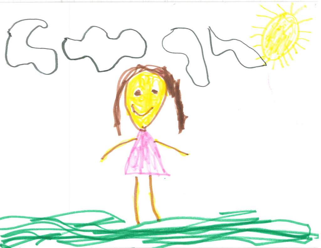
These ideas form an initial conceptual model of light. These are ideas that most people find easy to understand; they even are evident in the art of young children, who typically draw a sun as a circle with straight rays streaming out from the circle. Figure 1.10 is an example.
You can use these two central ideas to explain intriguing phenomena such as what happens when light passes through a tiny pinhole.
A. Exploring pinhole phenomena
Question 1.9 What happens when light passes through a tiny pinhole and shines on a screen?
There are many ways to explore what happens when light passes through a tiny pinhole. One way involves making a pinhole camera with materials typically available at home. This is called a camera but no photograph is made as no film is used in this exploration.
Equipment for each student: a toilet paper or paper towel roll, square piece of wax paper, square piece of aluminum foil, two rubber bands. Equipment for each small group: a push pin. A meter stick (or yard stick) and ruler also will be helpful in developing an explanation of what one sees when looking through such a pinhole camera at a bright light bulb in a dark room.
In a remote learning situation, students might have access to a paper cup or a cardboard box with a open end such as a snack box whose bottom can be made light tight with duct tape. Possible substitutions for the wax paper include a translucent cereal box liner or plastic vegetable bag from a grocery store to cover the open end. A chocolate bar liner might be a source of aluminum foil if a student has an empty paper roll with both open ends.
A student described making such a pinhole camera as follows:
First I laid the wax paper over one opening of the toilet paper roll and snuggly wrapped the edges down and secured the wax paper with a rubber band. I then laid the aluminum foil on the other end of the toilet paper roll and secured the edges of the aluminum foil with a rubber band. I took a push pin and made a single hole in the middle of the aluminum foil. I held the camera up so that the light from the light bulb on the table could shine through the pinhole in the aluminum foil and the wax paper faced me.
Physics student, Spring 2016
- Make a pinhole camera as described above.
- When you look through a pinhole camera at a bright light bulb in a dark room, what do you think you will see on the wax paper screen? Record your prediction and your reasoning in the Before section of your physics notebook page.
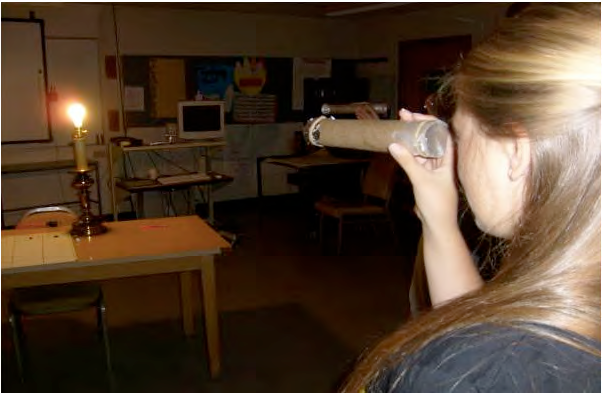
- After making a pinhole camera, darken the room and turn on a light bulb without a shade. Look at the light bulb through the pinhole camera. Hold the camera away from your face and point the aluminum foil end at the bulb as shown in Fig. 1.11. Move your hand around until you clearly see something on the wax paper screen. You may need to move closer or farther from the lamp.
- Also move your head from side to side while holding the camera steady. Does this change what you see on the wax paper screen? If so, how?
- Record what you are doing in the During section of your notebook page in both words and a sketch of the set up. Include a sketch of what you are seeing on the wax paper screen.
- Complete your entry on your physics notebook page before reading an example of student work about exploring pinhole phenomena.
1. Example of student work about exploring pinhole phenomena
Figure 1.12 shows what one sees when looking at a bright light bulb through a pinhole camera in a dark room.
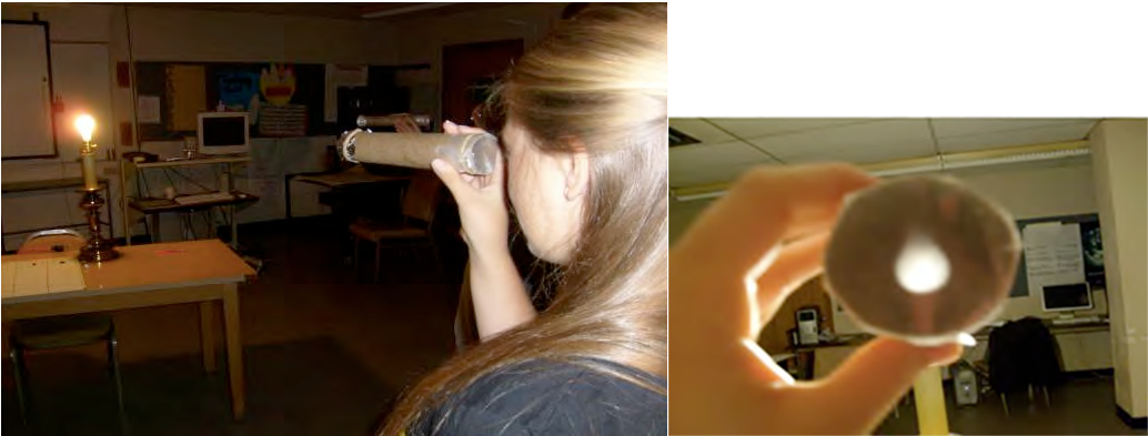
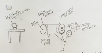
A student described the surprising effect visible on the wax paper screen:, “On the wax paper, I observed the projection of the light bulb but it looked like it was upside down!”
The student drew the sketch in Figure 1.13 to represent the set up and what was visible on the wax paper screen.
B. Explaining pinhole phenomena
After observing what is happening… and how something is happening, one likely will be asking a why question such as Question 1.10:
Question 1.10 Why are you seeing what you are seeing when looking at a bright light bulb through a pinhole camera in a dark room?
- Discuss with your group members some possible explanations for what you are seeing on the wax paper screen.
- Sketching what is happening can help suggest and evaluate ideas. Get a large white board or piece of chart paper and work together to sketch the ideas you have generated.
- Every so often step back and ask yourselves:*
- What you are doing?
- Why are you doing that?
- How is that helping you?
(*Alan Schoenfeld (1992) suggests this questioning sequence to help people help themselves stay aware of whether what they are doing is likely to be useful in solving a complex mathematics problem.)
- Draw the light bulb and its projection (what you are seeing on the wax paper screen).
- Omit drawing the camera itself; just draw the light bulb and its projection roughly parallel to each other and some distance apart.
- How can you use your conceptual model of light (the two central ideas developed so far) to explain why you are seeing what you are seeing on the wax paper screen?
How, for example, are light rays leaving the light source? Draw some rays.
How are some of these rays traveling from the light bulb to its projection on the screen?
- How can you use your physical model of light rays (meter stick or yard stick) traveling from one place to another to think about how light is getting from the top of the light bulb to where the top of the projected bulb is on the wax paper screen?
- Use your physical model of light rays to draw multiple rays traveling from various parts of the light source to where you are envisioning that they land on the screen to form the projection of the light bulb you are seeing.
In particular, draw rays leaving the top of the light bulb, the middle of the light bulb, and the bottom of the light bulb and traveling through the pinhole to form the projection of the bulb on the wax paper screen.
- Where is the pinhole located through which you are envisioning the light rays traveling from the source to the screen?
Represent the pinhole with an open circle and add the rest of the pinhole camera to your sketch.
- Do not erase the sketch that you have been drawing. This likely is quite messy. Admire it as a document representing some of your thought processes in developing this explanation of why you are seeing what you are seeing when light from a source passes through a pinhole to a screen.
- A careful drawing with straight lines showing how one is envisioning light rays traveling from one place to another is called a ray diagram.
On a new large white board or piece of chart paper, draw a careful ray diagram of this situation by using the meter stick to draw straight lines representing how you are inferring light rays leave the light bulb, travel through a tiny pinhole, and form a projection of the light bulb on the wax paper screen.
- In the “After” section of your physics notebook page, draw a careful ray diagram by using a ruler to draw straight lines to represent what happens when light passes through a tiny pinhole and shines on a screen.
- Also record new central ideas, the evidence that supports these claims, and a rationale that explains clearly why this happens.
- Also write a reflection about what you have learned.
- What are you still wondering?
Complete your entries on your physics notebook page before reading a student’s example response and some nuances about exploring, representing, and explaining pinhole phenomena.
1. Student’s example explanation of pinhole phenomena
In (Question 1.3 and 1.5), we discussed how light goes everywhere and that light rays travel in straight lines. With these ideas in mind, we inferred that all of the light rays that travel through the pinhole are traveling in straight lines. Because not all of these lines can travel straight forward, some of the lines end up traveling diagonally. As a result, the top of the light bulb gives off light rays that travel diagonally straight so that they travel through the pinhole and this diagonal line ends up projecting onto the bottom of the screen of the wax paper as shown by the blue line in (Fig. 1.14).
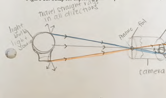
The light rays from the center of the light bulb travel straight forward through the pinhole and project the image of the center of the light bulb on the screen of wax paper.
The orange line in Fig. (1.14) shows that the light rays given off of the bottom of the light source travel in a straight line that is diagonal and projects onto the top of the screen of wax paper.
There are many light rays given off of the light bulb between the top and the bottom that all travel through the pinhole and project the image of the light bulb to appear upside down on the screen of wax paper.
Physics student, Spring 2016
The separate discussion of rays from the top, middle, and bottom of the light source is helpful when explaining pinhole phenomena. Also helpful is tracing each line with one’s finger while discussing each ray if one is talking about the ray diagram with someone just learning about these phenomena.
2. Some nuances in representing and explaining pinhole phenomena
Note that in the ray diagram in Fig. 1.14, the student has represented the pinhole as an open circle, where the lines representing the top, middle, and bottom light rays cross in the diagram. A filled-in circle would not be appropriate in a ray diagram representing pinhole phenomena because this would represent a solid barrier through which light rays could not pass. The student also used a ruler when representing light rays traveling in straight lines and put arrows on the lines to indicate the direction that the student was envisioning the light rays to be traveling.
Also note that in Fig. 1.14 the student has drawn some short rays that are leaving the top of bulb but are not heading toward the pinhole. This represents a further refinement of the first central idea about how light leaves a source.
Children’s drawings of the Sun typically show rays leaving the Sun in many directions as in Fig. 1.10. Each ray, however, seems to leave a point on the source in only one direction, straight outward. Such single rays are arrayed around the circle representing the Sun. This conception of how light leaves a source prompts an issue in explaining pinhole phenomena: if rays only leave in a perpendicular direction from a source, how can any rays from near the top of the bulb be traveling at an angle, diagonally downward, toward the pinhole?
One way to address this issue is to cover the light bulb with aluminum foil or a dark cloth so that light only shines out from a hole near the top of the bulb. Does light shine from the hole only in one direction perpendicular to the surface there? Or are the ceiling, floor, walls of the room and people’s faces still lit, at least dimly? If so, this suggests an additional refinement to the first central idea: light leaves a point on most sources in many directions. This is an example of an aspect of the nature of science articulated in the US Next Generation Science Standards that science is open to revision in light of new evidence (NGSS, Lead States, 2013, Appendix H, https://www.nextgenscience.org/resources/ngss-appendices ).
The student who drew Fig. 1.14 seems to be grappling with this issue in the language used: the top of the light bulb gives off light rays that travel diagonally straight so that they travel through the pinhole. This student’s language also illustrates a nuance that sometimes confuses students: the meaning of the word straight. For some people, straight only means horizontal rather than the more general meaning of without any bends. This student invented the phrases straight forward to mean traveling horizontally without bends, as in the center gray rays, and diagonally straight to mean traveling at an angle without bends, as in the top blue rays and the bottom orange rays. Such elaboration is not required in this course; simply discussing light as envisioned as rays traveling in straight lines is sufficient.
It is important to realize that nothing happens within the pinhole. This explanation envisions the light rays as simply passing through the pinhole in a straight line on their way to where they are going, some light rays from the top of the bulb traveling straight through the pinhole to near the bottom of the screen, some light rays from the middle of the bulb traveling straight through the pinhole to near the middle of the screen, and some light rays from the bottom of the bulb traveling straight through the pinhole to near the top of the screen. The light rays are envisioned as simply passing through the pinhole on their way to separate places on the screen.
Sometimes students use the word flipped to refer to the upside down projection that they see on the screen. This word is not appropriate here, however, because it suggests that something happened to the rays to cause a flip but nothing happens to flip the rays that form the projection. The rays forming the upside down projection are envisioned as simply continuing to travel in straight lines from the source through the pinhole toward the screen. One can see the upside down bulb because the aluminum foil blocks other rays from traveling to the screen.
A confusion also can occur over the use of the word projection. Does the phrase top of the projection refer to what one sees near the top of the screen (which is the projection of the bottom of the bulb) OR does the phrase top of the projection refer to the projection of the top of the bulb (which occurs near the bottom of the screen)? To avoid confusion, it is important to use the cumbersome but clear phrase “where these light rays form the projection of the topof the bulbnear the bottom of the screen.” The word projection is preferred over the word image here as the word image in physics typically refers to different light phenomena involving mirrors and lenses.
Like adults, children typically are surprised and intrigued by seeing an upside down light bulb when they look through a pinhole camera. As indicated by their drawings of the sun, children already know the key idea for understanding pinhole phenomena, that light can be envisioned as rays traveling in straight lines.
When discussing pinhole phenomena, with both children and adults, it is helpful to use a finger to trace the line on a ray diagram while discussing how rays from a particular part of the source are traveling:
Some light rays from the top of the light bulb are traveling straight through the pinhole to form the projection of the top of the light bulb near the bottom of the screen,
Some light rays from the middle of the light bulb are traveling straight through the pinhole to form the projection of the middle of the light bulb near the middle of the screen,
Some light rays from the bottom of the light bulb are traveling straight through the pinhole to form the projection of the bottom of the light bulb near the top of the screen and
Some light rays from all up and down the light bulb are traveling straight through the pinhole to form the rest of that upside down projection of the light bulb on the screen.
C. Exploring a critical issue
Missing from the discussion so far is a critical issue, how is information about what is happening getting to an observer?
Question 1.11 How does someone see this projection on the screen?
- Look again at what you see when looking at a bright light bulb through a pinhole camera.
- Hold the camera steady while moving your head from side to side. Does your view of the projection change? If so, how? What does this imply about how light travels through translucent materials such as the wax paper screen?
- Also consider what has to happen for someone to see something: How did the light rays get from the projection on the wax paper screen to your eye?
- Where on your ray diagram would you represent your eye looking at the projection on the screen?
- How would you represent on the ray diagram what is happening when you see the projection on the screen?
Complete your entry on your physics notebook page and Table 1 (continued). Then write a summary of what you have learned before reading example student work explaining how one sees pinhole phenomena.
| TABLE I.1 Explorations of light phenomena (continued) | |||
|---|---|---|---|
| Description of Exploration | Evidence Observed | Central Ideas | Vocabulary |
| Light rays emerge from translucent material (such as wax paper) in many different directions | translucent | ||
| For someone to see something, light has to get to the person’s eyes. | |||
1. Example of student work about how one sees the projection on the screen
A student reported, “I was still able to see the projection on the wax paper when I would move my head from side to side” and offered an explanation “We are able to see the image even when we move our head because the light rays travel in many directions as they emerge from the translucent wax paper so some of them still travel to our eyes.”
This student was invoking two additional central ideas developed in class:
Light rays emerge from translucent material (such as wax paper) in many different directions. Some of those directions are toward the eye.
For someone to see something, light has to get to the person’s eye.
The student added an eye to the ray diagram, with straight lines from the projection to the eye to represent light leaving the projection and traveling to her eye as shown in Fig. 1.15.
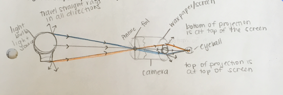
The student explained the complete ray diagram as follows:
The orange line represents light rays traveling from the bottom of the light bulb through the pinhole to the top of the screen and then some of the rays travel in a straight line to the eyeball.
The middle grey line represents the light rays that travel from the center of the light bulb through the pinhole, creating the image of the middle of the bulb on the screen, then some travel to the eyeball.
The blue line represents the light rays that travel straight from the top of the light bulb diagonally down through the pinhole and then project the image of the top of the light bulb onto the bottom of the screen of wax paper. Some of the blue rays then travel …to the eyeball.
The notes added near the top and bottom on the right side of this diagram illustrate the confusion of the meaning of the word projection – does this refer to what one is seeing? (bottom of the bulb near the top of the screen) or to the entity itself ( the top of the projection refers to what is at the top of the screen)? In this course, avoid the phrases “bottom of projection” and “top of projection” and use instead the clear phrase “where these light rays form the upside down projection of the top of the bulb near the bottom of the screen.”
D. Exploring variables affecting pinhole phenomena
Another type of question focuses upon identifying what is important to notice in a situation:
Question 1.12 What variables affect what one is seeing on the screen?
- Discuss with your group members ways you can change the pinhole camera you made and ways that you are using it.
- Also consider making new ones such as comparing what happens when one uses an empty toilet paper roll, paper towel roll, or holiday wrapping paper roll.
- Another possibility is to make an “open” pinhole device without an enclosing body. Make a pinhole holder by cutting out an area within a piece of cardboard, taping a “cover” of Aluminum foil over the area, and poking a hole in the Al foil. Make a firm screen by taping a piece of copy paper to a piece of cardboard the same size. Then hold the pinhole holder in one hand and the firm screen in the other hand in front of a lamp without a shade until you see the upside down projection. Then observe how the projection changes as you change how you hold the pinhole holder and screen with respect to the lamp.
- Explore and report on some of these possibilities in Table I.2
| TABLE I.2 Variables in exploration of pinhole phenomena | |
|---|---|
| Variable | Observation |
- In the “After” section of your physics notebook page, record two new central ideas, the evidence that supports these claims, and a rationale that explains how the evidence supports the ideas and why these are important.
- Also write a reflection about what you have learned.
- What are you still wondering?
Complete your entry on your physics notebook page and write a summary of what you have learned before reading examples of student work of exploring variables that affect pinhole phenomena
1. Example of student work about variables that affect pinhole phenomena.
How big is the projection? How bright is it? How sharp is it? How many projections does one see? Do distance from the light source, length of the roll, size of the pinhole, shape of the light fixture, or number of pinholes matter? As shown in Fig. 1.16, a student included the following variables in reporting findings: distance from light, multiple pinholes, size of camera roll, larger pinhole, and light fixtures of different shapes:

This student then described these findings using “projected image” rather than the more technically preferred “projection.” The multiple examples illustrate well, however, the many ways even young students can enjoy exploring pinhole phenomena:
When the distance between the camera and the light bulb increases, the projected image of the light bulb on the wax paper screen becomes smaller. When there are multiple pinholes in the aluminum foil, there will be multiple projected images of light bulbs on the screen of wax paper. When the length of the paper roll of the camera increases, the projected image of the light bulb gets larger. When the pinhole is made into a larger hole, the image becomes larger and fuzzier, it is more difficult to tell if the image is still upside down or not.
When the camera is used to view light bulbs of different shapes, the projected image of the light bulb on the wax paper screen will change with the light fixture. For example, in class we looked at a light bulb that was similar to a tear drop shape and our projected image looked similar to an upside down teardrop. When I used the camera on a spherical light fixture, the projected image looked like an upside down circle. Some other questions that I have is: is this how our pupils work? How did people discover the pinhole phenomena?
Physics Student, Spring 2016
In this course, we are not exploring what happens within the eye, just getting light to the eye. If you are wondering what happens next, after the light enters the eye, consult a book or internet website about how eyes work such as https://nei.nih.gov/kids/about_the_eye .
The eye’s pupil acts like a pinhole with a variable diameter that controls how much light enters the eye. The projections on the retina are upside down and are turned ‘right side up’ by your brain. Some additional information about how the eye works is at: http://www.mind.ilstu.edu/curriculum/vision_science_intro/vision_science_intro.php
Some historical information about pinhole cameras is at https://jongrepstad.com/pinhole-photography/pinhole-photography-history-images-cameras-formulas/
E. Exploring pinhole phenomena with friends and/or family members
Question 1.13 What happens when exploring pinhole phenomena with a friend or family member
- Continue exploring pinhole phenomena outside of class with a friend or family member.
- Complete your entry on your physics notebook page and write a summary of what you have learned before reading examples of student work exploring pinhole phenomena with friends and/or family members .
1. Examples of student explorations of pinhole phenomena with friends and/or family
A student explored pinhole phenomena with a cousin:
I showed the pinhole phenomena with my 15 year old cousin. Before seeing the projection he guessed that the projection on the wax paper would be the shape of the pinhole. When he saw the projection his exact words were “what the fudge?”
It took Z. a moment to realize what he saw was an upside down light bulb. When asked why he thought the projection was upside down he said “I have no idea…. I don’t even know how it is projecting the stupid light bulb!”
I then asked Z. what he knew about light; after some discussion he and I came to the conclusion that light travels in all directions and that light travels in straight lines called rays.
I asked Z. to draw on a whiteboard a representation of what he saw, much like what I myself did in class with my group. Z. did so, and I then asked him to use a ruler and his pen to draw rays leaving the light bulb. At first Z. drew only light rays leaving in vertical and horizontal lines. I then asked Z. to tell me again how light travels. Z. said that it travels in all directions in straight lines. I asked him to show me lines that traveled in all directions, so Z. drew more lines leaving the bulb in all directions much like the lines above.
I then posed the question to Z. of how light was getting through the tube and onto the screen. Something seemed to click with Z. then because he erased his original drawing and drew a new bulb with about 10 rays some of which went through the pinhole and onto the screen. He then told me that since the rays that he drew at the top of the bulb “would continue traveling on their downward path and would be projected onto the bottom of the screen. The lights from the bottom of my bulb will travel towards the top and be projected there. Is that right?”
I was honestly amazed at how quickly he picked up on the information. I told him he was right and showed him my own ray diagram and he said that it made sense. He then helped me find ways to alter the experiment, which are shown in table 2.
From my experience working with and teaching Z. I realized how frustrating it can be to work with older students. I do not mean for this to sound bad, because in some ways it was refreshing to work with an older student. Yet, as I worked with Z. I found that I am so accustomed to working with younger children, these children need a certain amount of guidance, more so than he did. Z. did need my help to understand but much of what he was able to figure out on his own was frustrating and interesting to me. His mind works so quickly and he needed only a slight push in the right direction to understand. Knowing this it was hard to hold my tongue and not explain everything to him before allowing his mind to make the connections first.
Physics student, Fall 2015
Another student chose to explore pinhole phenomena with a roommate:
I explored pinhole cameras with one of my roommates. I began by asking her what she knew about light (such as the direction it travels, whether or not it travels in a straight line). To my surprise she already knew that light traveled in all directions and in a straight line. I told her to keep that in mind.
I then showed her the pinhole camera I had made in class and explained what she would be doing with the light bulb and the camera. Before turning on the light bulb I asked her what she thought would happen. She said that she thought the light bulb would appear on the wax paper.
I then turned on the light bulb and asked her to look and tell me what she saw. She was puzzled to find that the light bulb that appeared on the wax paper was actually upside down. She could not tell me why this happened.
I gave her a piece of paper and pencil and asked her to draw the entire set up including what she had seen. I then asked her again to tell me what she knew about light. When she said that light traveled in a straight line I told her to stop and think about that.
She thought for a few seconds and then told me that light was entering the pinhole camera in a straight line. I encouraged this by giving her a ruler to add some straight light rays to her picture. After drawing straight lines for a few seconds she connected the top of the light bulb to the bottom of the light bulb on the camera with a straight line. She did the same for the bottom of the light bulb. I asked her to tell me what this meant. She explained that the ray coming from the top of the light bulb travels in a straight line through the pin hole to the bottom of the screen and the ray coming from the bottom of the light bulb does the same, except it appears at the top of the screen.
I learned that being patient and providing my roommate with adequate thinking time (private reasoning time), she was able to tell me exactly what had happened. I prompted her throughout the experiment with questions instead of telling her the answers. I also encouraged her to build off of what she already knew (for example: that light travels in a straight line).
Physics student, Spring 2014
This concludes this example of using central ideas based on evidence to explain intriguing phenomena.

